


1. Introduction: The Growing Demand for Large-Aperture Aspheric Mirrors
With the rapid advancement of space optics and astronomical optics, the demand for large-aperture aspheric mirrors continues to surge. However, the inherent brittleness of optical materials and the stringent surface accuracy requirements impose significant manufacturing challenges, including low processing efficiency, long cycle times, and inconsistent surface quality.
The current mainstream aspheric surface fabrication technologies include:
Computer-Controlled Optical Surfacing (CCOS)
Bonnet Polishing
Magnetorheological Finishing (MRF)
Active Lap TechnologyBased on tool characteristics, these technologies can be broadly categorized into rigid-body processing and compliant-body processing. Among them, active lap technology, as a controllable compliant-body approach, stands out for its high material removal rate and excellent mid-to-high spatial frequency error suppression, making it one of the most effective solutions for large-aperture optical element fabrication.

2. Working Principle and Structural Composition of the Active Lap
2.1 Core Structure
The active lap system comprises four major modules:
Grinding Disc: Located at the bottom of the system, consisting of a circular metal plate and grinding material. It directly contacts the optical workpiece and performs the material removal function.
Deformation Drive Unit: Positioned at the upper edge of the disc, comprising 4 groups of 12 drive motors in total. Each group contains three equally spaced motors interconnected by elastic chains, with force sensors providing real-time feedback for closed-loop force control.
Weight-Reduction System: Consisting of three equally spaced electromechanical units, each equipped with a motor, lead screw, tension sensor, and spring. By adjusting the lead screw elevation, grinding pressure can be modulated to enable variable-pressure or zero-pressure grinding modes, balancing processing efficiency and subsurface damage control.
Control System: Coordinates all modules to ensure the lap surface conforms to the target profile in real time.
2.2 Operating Principle
The active lap employs active deformation technology, using computer-controlled actuators to dynamically shape the disc surface during radial translation and rotation. The lap profile continuously and in real time matches the theoretical aspheric surface, enabling high-efficiency, high-precision grinding and polishing.
The key advantages include:
Deterministic Processing: Both the removal function and the tool path are precisely controllable, ensuring process determinism.
High Surface Quality: The lap surface consistently conforms to the ideal workpiece profile, effectively suppressing mid-to-high spatial frequency errors.High Efficiency: The large-aperture lap generates a large removal footprint, resulting in short processing cycles and rapid surface convergence.

3. Multi-Source Analysis of Static Deformation Errors
3.1 Root Causes of Error
Under actual operating conditions, the deformation of the active lap inevitably deviates from its ideal value due to computational inaccuracies, mechanical fitting tolerances, actuator nonlinearity, and precision limitations, all of which severely compromise the final processing accuracy.
3.2 Four Categories of Error Sources
Based on the stage at which errors arise, the static deformation errors of the active lap can be classified into four major categories:
Error Category
Generation Mechanism
Mathematical Characteristic
Computational Error
Numerical errors introduced by truncation of the generalized inverse matrix during force calculation
Tends toward constant offset
Modeling Error
Discrepancy between the influence function (IF) and actual physical response
Exhibits linear characteristics
Execution Error
Secondary deviations in motor driving force caused by sensor nonlinearity
Manifests as quadratic function effects
Structural Error
Stress concentration at features such as the central hole and edge cross-sections
Directly correlated with stress concentrationThis multi-source coupling characteristic constitutes the core technical challenge in active lap error compensation.

4. Zone-Based Error Prediction and Compensation Method
4.1 Zone-Based Modeling Strategy
To accurately characterize the error distribution patterns across different regions of the lap surface, a zone-based error prediction model is proposed. The procedure is as follows:
Annular Zone Division: Based on sampling point distribution, the disc surface is divided into four concentric annular zones.
Stress-Based Classification: According to stress distribution characteristics, the zones are further categorized into primary deformation zones (high stress concentration) and low deformation zones (low stress concentration).
4.2 Special Treatment of the Low Deformation Zone
The third annular zone is located near the radial center of the disc, where stress concentration effects are minimal. In this region, deformation errors are no longer dominated by a single stress effect but arise from the balanced interaction of multiple factors, including driving force errors, mechanical transmission errors, and stress field interference. This makes the error evolution highly unstable. Additionally, the error magnitude in this zone approaches the displacement sensor’s resolution limit (approximately 0.5 μm), resulting in a significantly reduced measurement signal-to-noise ratio. Therefore, this zone requires a distinct fitting strategy.
4.3 Differentiated Fitting Approach
Primary Deformation Zones: A quadratic polynomial model with zero-position constraints is employed to fit local deformation errors at surface feature points, comprehensively accounting for the evolution characteristics of computational, modeling, and execution errors.
Low Deformation Zone (Third Annular Zone): A constant model is adopted, using the mean value of the prediction set at each feature point as the final predicted value. This prevents over-compensation artifacts that would result from forcibly fitting high-oscillation, small-amplitude data.
4.4 Compensation WorkflowThe overall compensation pipeline is: comprehensive error source analysis → construction of a global feature-point displacement prediction function based on measured data → derivation of corrected driving forces using the modified target surface as input → closed-loop compensation of static deformation errors.

5. Experimental Validation and Results
5.1 Experimental Setup
Test Subject: Active lap with an aperture of 530 mm
Simulated Working Condition: Processing environment for a 2 m aperture, F/1.7 parabolic mirror
Measurement System: Proprietary 53-channel array contact displacement measurement system
5.2 Key Findings
The experimental results demonstrate that:
After applying the proposed error compensation method, the lap surface residual errors were significantly reduced compared to the uncompensated state.The static deformation surface residual RMS was consistently controlled within 1 μm, confirming the engineering effectiveness of the proposed approach.

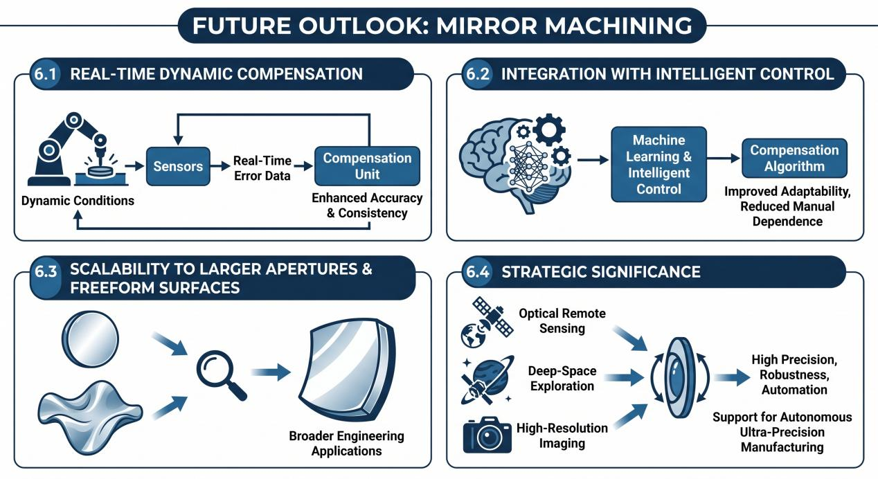
6. Future Outlook
6.1 Real-Time Dynamic Compensation
The current research focuses on static deformation error compensation. A critical future direction is achieving real-time error compensation under dynamic processing conditions to further enhance machining accuracy and consistency.
6.2 Integration with Intelligent Control
Incorporating machine learning and intelligent control into the compensation algorithm is expected to improve the adaptability and generalization capability of error prediction, reducing dependence on manual expertise.
6.3 Scalability to Larger Apertures and Freeform Surfaces
Validating the model’s scalability on larger-aperture mirrors and more complex freeform surface machining tasks is essential for advancing this technology toward broader engineering applications.
6.4 Strategic Significance
As cutting-edge applications in optical remote sensing, deep-space exploration, and high-resolution imaging continue to raise the bar for mirror surface accuracy, active lap technology will inevitably evolve toward higher precision, greater robustness, and higher levels of automation. This progression will provide solid technical support for the autonomous ultra-precision manufacturing of large-aperture optical elements.