


1. Technical Background of Single-Crystal Silicon Optical Element Machining
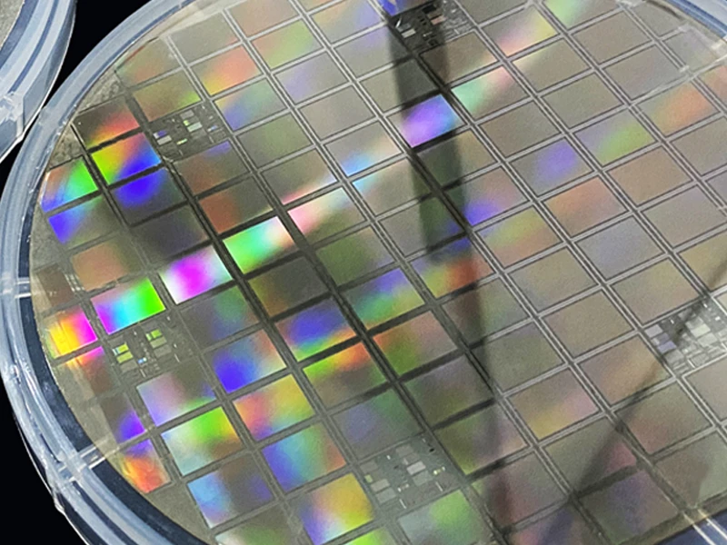
Single-crystal silicon, owing to its excellent infrared transmittance, superior mechanical properties, thermal stability, and chemical stability, is widely used in infrared optical systems, laser systems, spectrometers, and optical windows. With the rapid development of aerospace, precision instrumentation, and high-end equipment manufacturing, the requirements for surface form accuracy and surface quality of single-crystal silicon optical elements have become increasingly stringent.However, single-crystal silicon possesses high hardness, high brittleness, and anisotropic machining characteristics, which pose severe challenges to ultra-precision machining. How to achieve nanometer-level surface accuracy and subsurface damage control has become a core research issue.

2. Limitations of Conventional Machining Processes
2.1 Shortcomings of Traditional Grinding-Lapping-Polishing Process
The traditional machining route follows the concept of “damage first, then remove,” typically proceeding through grinding → lapping → polishing. This approach has the following problems:
The subsurface damage depth generated during the grinding stage is significant (typically in the micrometer to tens-of-micrometer range), requiring extensive time for removal during subsequent lapping and polishing
The small-tool polishing stage accounts for more than 60% of total processing time, resulting in low efficiency
Lapping is a non-deterministic machining method, making surface form accuracy difficult to control precisely
2.2 Limitations of Ultra-Precision Grinding
Although ultra-precision grinding can effectively suppress subsurface damage on flat surfaces, it still faces challenges in complex curved surface machining:
Subsurface damage on complex curved surfaces has not been fully resolved
Grinding wheel size constraints prevent machining of small-sized deep concave structures and complex surfaces
2.3 Issues with Conventional Ultra-Precision CuttingWhile ultra-precision cutting offers more flexible complex surface machining capabilities, when processing hard-brittle materials, diamond tools are extremely susceptible to wear, further compromising the form accuracy and surface quality of optical elements.

3. Short-Process Machining Strategy
To address the aforementioned issues, a short-process machining workflow combining laser in-situ assisted ultra-precision turning, magnetorheological finishing (MRF), and small-tool polishing is proposed. The core concept is to achieve full-process suppression and removal of subsurface damage while simultaneously obtaining high form accuracy, high surface quality, and improved machining efficiency.
The process flow consists of:
Laser in-situ assisted ultra-precision turning — forming while suppressing subsurface damage
Magnetorheological finishing (MRF) — efficient surface form error correctionSmall-tool polishing — surface quality enhancement and form-preserving polishing

4. Laser In-Situ Assisted Ultra-Precision Turning Technology
4.1 Technical Principle
Laser in-situ assisted ultra-precision turning applies a flat-top laser beam to locally heat the cutting zone, softening the single-crystal silicon material and reducing its strength and hardness. This significantly increases the brittle-to-ductile transition critical depth of the hard-brittle material, enabling ductile-mode cutting.
4.2 Process Parameters
Actual laser power reaching the workpiece surface: 2 W
Spot diameter: 200 μm
Flat-top laser-assisted turning apparatus employed
4.3 Subsurface Damage Suppression Results
Transmission electron microscopy (TEM) inspection reveals that the cross-section of machined samples consists of three distinct layers:
Top protective layer (residual from sample preparation)
Middle amorphous layer (generated by turning)
Bottom defect layer (containing various subsurface defects)
Comparative results show:
The subsurface damage after laser-assisted cutting exhibits distinct dislocations and nanoscale damage zones, demonstrating typical ductile-mode cutting characteristics. The subsurface damage depth is reduced by 65.4%.
4.4 Post-Turning Machining Quality
Measured by Computer-Generated Hologram (CGH) interferometry and white light interferometry:
Surface form accuracy RMS: 49.417 nm (better than 1/12 λ)Surface roughness Ra: 1.231 nm (better than 2 nm)

5. Combined MRF and Small-Tool Polishing Technology
5.1 Magnetorheological Finishing (MRF)
MRF utilizes a deterministic removal function for surface form correction. Key steps include:
Based on measured removal functions, employing the convolution iterative method through deconvolution to calculate dwell times at different positions
Machining the workpiece along a raster scan trajectory
Direct polishing is possible due to the good form accuracy achieved after turning
5.2 Small-Tool Polishing
After MRF, the workpiece surface may exhibit polishing fluid residues and characteristic surface scratches, necessitating subsequent small-tool polishing. The core of small-tool polishing technology lies in:
Precise control of dwell time
Proper regulation of pressure between the polishing tool and workpiece
Computer-controlled tool path, dwell time, and polishing pressure parameters
5.3 Iterative Machining StrategyThrough multiple iterations of MRF form correction and small-tool form-preserving polishing, the respective advantages of MRF’s high-efficiency form correction and small-tool polishing’s form preservation are fully leveraged, achieving efficient convergence of surface form accuracy and surface quality for complex curved single-crystal silicon elements.

6. Final Machining Results
After the complete short-process workflow, the single-crystal silicon off-axis reflective optical element achieves the following specifications:
Specification
Final Result
Full-aperture surface form accuracy RMS
Better than 1/50 λ (approximately 12.6 nm)
Surface roughness Ra
Better than 0.5 nm

7. Summary of Technical Advantages
This short-process machining workflow offers the following significant advantages over conventional processes:
Full-process subsurface damage suppression: Laser-assisted turning substantially reduces subsurface damage depth at the initial stage, minimizing subsequent polishing removal time
Significantly improved machining efficiency: Eliminates the lengthy and inefficient traditional grinding-lapping-polishing workflow
Strong complex surface machining capability: Ultra-precision turning overcomes grinding wheel size limitations, enabling machining of small-sized deep concave structures
Simultaneous high form accuracy and surface quality: The combined polishing strategy achieves high form accuracy (RMS better than 1/50 λ) and nanometer-level surface roughness (Ra better than 0.5 nm)
Meets high-precision optical element application requirements: Applicable to aerospace, precision instrumentation, and other high-end fields
