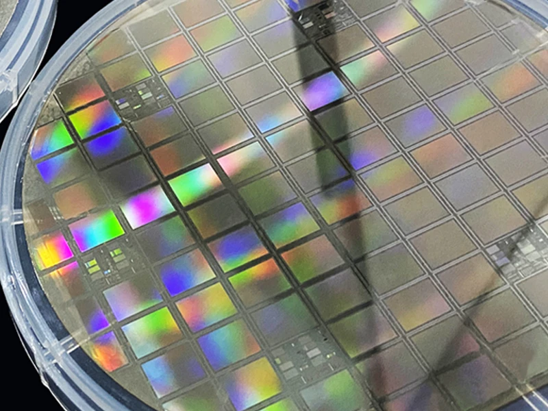


In the wafer manufacturing process, scribe line and saw line are two critical concepts that play vital roles in the back-end wafer processes. For easier understanding, we can compare a wafer to a large cake, where each chip is like a slice cut from the cake—scribe lines and saw lines act as the “guides” and “paths” for cutting these slices.
1. Scribe Line
Definition
A scribe line is a series of narrow, blank areas on the wafer surface that separate different chip regions. It is not part of the chip’s actual circuitry but serves as a physical dividing line, functioning to space out individual chips on the wafer.

Functions and Characteristics
- Physical Separation: Typically located between chips, scribe lines form a “buffer zone” that ensures each chip can be separated individually during subsequent cutting without mutual interference.
- Designed Position: Scribe lines are usually designed as blank areas with no circuitry. Their position and width are determined during the wafer design phase to guarantee precise separation of each chip during cutting.
- Facilitating Cutting: Scribe lines provide a clear reference for subsequent wafer cutting processes (e.g., laser cutting or blade dicing), helping maintain accuracy and consistency during wafer singulation.
2. Saw Line
Definition
A saw line refers to the actual path used for mechanically cutting the wafer into individual chips. It is typically a groove created by precision dicing equipment along the scribe line, essentially the area of the wafer where physical separation occurs.

Functions and Characteristics
- Cutting Path: The saw line is the actual area where cutting takes place, usually performed by a dicing blade or laser cutting tool. It is generally wider than the scribe line and contains no chip circuitry, serving as a clear physical zone for cutting.
- Cutting Process: The area defined by the saw line undergoes the subsequent “dicing” process to split the wafer into individual chips (also called dies). This process requires highly precise equipment to ensure the integrity and functionality of the circuitry after separation.
- Spacing Between Chips: Precise control of the saw line position ensures appropriate spacing between chips during cutting, preventing damage to the finished chips.
3. Relationship Between Scribe Line and Saw Line
- Different Functions, Close Coordination: The key difference lies in their roles: scribe lines are designated reference zones that provide physical space or guidance for subsequent cutting, while saw lines are the actual physical paths for chip separation. During production, scribe lines typically guide the cutting path of saw lines, enabling precise chip singulation.
- Process Connection: Generally, scribe lines serve as design references to guide cutting machines to the correct positions. Saw lines, in turn, are the actual execution paths for final chip separation in the wafer manufacturing process.
4. Width of Scribe Line and Saw Line
- Scribe Line Width: Usually extremely narrow. Its design ensures it does not affect chip function or quality—it only provides guidance for subsequent cutting and contains no chip circuitry.
- Saw Line Width: Relatively wider, typically ranging from several micrometers to tens of micrometers, depending on the cutting technology and equipment used. A wider saw line increases cutting errors and material loss.
5. Optimization of Scribe Line and Saw Line
- Reducing Material Loss: As wafer sizes continue to increase, optimizing scribe lines and saw lines becomes particularly important. Minimizing edge loss per chip and refining the design of these lines directly impacts final chip yield and production efficiency.
- Application of Large-Diameter Wafers: To reduce waste of edge chips, the semiconductor industry is gradually adopting larger-diameter wafers. The design of scribe lines and saw lines is adjusted accordingly on larger wafers to improve chip utilization.
6. Summary
Scribe lines are reference zones on the wafer that separate individual chips, ensuring proper spacing during cutting. Saw lines, by contrast, are the actual cutting paths that determine chip separation and dimensions. Working in tandem, they enable efficient and precise singulation of wafers into individual chips while minimizing material waste and manufacturing errors.