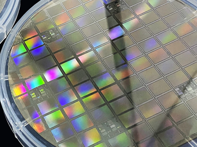


Silicon wafers after multi-wire cutting feature extremely sharp edges with burrs, edge chipping and even microcracks. This state poses three major problems in semiconductor manufacturing:
1. Prevent Edge Chipping and Contamination
Silicon wafers are brittle, and their sharp edges are prone to microcracks or even chipping with a slight impact during handling, transfer or subsequent processes.
These debris turn into contaminant particles that spread in the clean room, scratching the silicon wafer surface, damaging photolithography masks, and causing defects such as pinholes and poor exposure, which severely reduce the production yield.
2. Alleviate Thermal Stress Concentration
In high-temperature processes (e.g., oxidation, diffusion), sharp edges lead to local concentration of thermal stress, which may exceed the bearing limit of the silicon crystal lattice.
This generates crystal defects such as dislocations and stacking faults at the wafer edges, which propagate inward, impairing the electrical performance of devices and even causing wafer breakage and scrapping.
3. Improve Film Uniformity
In processes such as epitaxial growth or photoresist coating, material accumulation or protrusions easily form at acute edge angles due to surface tension or differences in growth rate.
This results in uneven film thickness, affecting photolithography focusing and pattern transfer quality, and reducing chip performance.
Typical Operational Process of Silicon Wafer Chamfering
Combined with practical production processes, the typical process of silicon wafer chamfering is as follows:
1. Wafer Clamping
A robotic arm takes the silicon wafer out of the cassette and places it on the vacuum chuck of the workbench;
The vacuum chuck holds the wafer firmly to prevent loosening during rotation;
Adjust the wafer position to align its edge with the grinding wheel.
2. Centering and Thickness Measurement
The conveying mechanism moves the workbench to the position below the measuring station;
The lifting mechanism raises the wafer to the measuring station;
The centering sensor measures the current center of the wafer, compares it with the set center, and automatically adjusts the workbench position to align the wafer center with the rotation axis;
The thickness gauge measures the wafer thickness to provide a benchmark for subsequent grinding amount control.
3. Rough Chamfering (Rapid Material Removal)
The conveying mechanism moves the workbench to the position below the grinding station of the grinding wheel mechanism;
The lifting mechanism raises the wafer to the grinding position of the grinding wheel groove;
The wafer rotates at a certain speed, and the grinding wheel spins at a higher speed (usually 6000–8000 r/min);
The grinding wheel slowly cuts into the wafer edge for rough grinding, rapidly removing material and shaping the edge profile;
Coolant is continuously sprayed to the grinding area to dissipate heat and remove swarf.
4. Fine Chamfering (Precision Polishing)
After rough chamfering, replace or switch to a fine-grained grinding wheel;
Reduce the grinding depth and feed rate for precision grinding;
The purpose of fine chamfering is to reduce edge roughness, smooth the edge surface, and reduce particle contamination in subsequent processes.
5. Cleaning and Spin-Drying
After chamfering, the robotic arm removes the wafer from the vacuum chuck and places it on the cleaning and spin-drying station;
Cleaning liquid rinses the wafer surface to remove grinding swarf and coolant residues;
The spin-drying program dries the water on the wafer surface to prevent water stain residues.
6. Diameter Measurement and Cassette Return
Measure the wafer diameter and the position of the orientation flat/notch to verify the chamfering quality;
The robotic arm returns the wafer to the cassette, ready for the next process step.